Difference between revisions of "LC-EM-1085"
(Created page with "==Product Name== CANdleLight USB to CAN module can debugging assistant can bus analyzer<br> ==About== The Aisai CANdleLight USB to CAN module is ported from an open-sour...") |
|||
| (4 intermediate revisions by the same user not shown) | |||
| Line 1: | Line 1: | ||
==Product Name== | ==Product Name== | ||
| − | + | CAN Expansion Board ARDUINO CAN Automotive Communication Protocol Analysis and Learning Module<br> | |
| Line 8: | Line 8: | ||
==About== | ==About== | ||
| − | + | LC CAN module has become the preferred choice in embedded system design due to its excellent performance and flexibility | |
| + | |||
| + | It adopts MCP2515 CAN controller and NXP CAN protocol chip, and the combination of the two ensures the efficiency and stability of the module in CAN communication protocol | ||
| + | |||
| + | By seamlessly integrating with Arduino, developers can quickly build powerful devices such as CAN protocol analyzers and data transceivers | ||
| + | |||
| + | The module design is well considered, with two reserved button interfaces, providing convenience for user operation | ||
| + | |||
| + | In addition, it is equipped with IIC interface and serial port, further expanding the module's connectivity and application scenarios | ||
| + | |||
| + | Whether in the fields of industrial automation, automotive electronics, or smart homes, this CAN module can help your project quickly integrate and develop CAN communication with its efficient and reliable performance | ||
| Line 17: | Line 27: | ||
<big>'' Front view ''</big><br> | <big>'' Front view ''</big><br> | ||
| − | [[Image: | + | [[Image:MCP2515-01.png]]<br><br> |
<big>'' Side view ''</big><br> | <big>'' Side view ''</big><br> | ||
| − | [[Image: | + | [[Image:MCP2515-02.png]]<br><br> |
<big>'' Reverse image ''</big><br> | <big>'' Reverse image ''</big><br> | ||
| − | [[Image: | + | [[Image:MCP2515-03.png]]<br><br> |
| Line 32: | Line 42: | ||
==Introduction and Explanation== | ==Introduction and Explanation== | ||
| − | Board size: | + | Board size: 68.5 * 53.5mm/28g<br> |
| − | [[Image: | + | [[Image:MCP2515-06.png]]<br><br> |
| − | |||
| − | |||
| − | |||
| − | |||
==Functional Features== | ==Functional Features== | ||
| − | * | + | *Perfectly compatible with Arduino UNO, enabling developers to easily integrate with Arduino UNO. This design not only simplifies the process of hardware connection, but also greatly expands the functional boundaries of Arduino |
| − | * | + | *The module is equipped with a serial port indicator light, which visually displays the communication status of the data transmission and reception process, ensuring transparency and real-time operation |
| − | * | + | *CAN data can be input through a 9-pin serial port or wiring terminal, which can meet the needs of different scenarios |
| − | |||
| − | |||
| Line 58: | Line 62: | ||
==Instructions for use== | ==Instructions for use== | ||
| − | + | Refer to the schematic diagram and use the PSI interface to communicate with Arduino. You can search for a suitable Arduino library to drive MCP2515. The reference program uses acan2515<br> | |
| − | |||
| − | |||
| − | |||
| − | |||
| − | |||
| − | |||
| − | |||
| − | |||
| − | + | Connect as shown in the diagram, power on to burn the reference program, press the SW1 button, and the CAN module will generate data<br> | |
| + | It is recommended to use it in conjunction with a USB to CAN analyzer, as the data generated can be seen on the upper computer<br> | ||
| + | Send data from USB to CAN host computer to Arduino, and Arduino can print out the received CAN data<br> | ||
| + | [[Image:MCP2515-04.png|600px|]]<br><br> | ||
| + | [[Image:MCP2515-05.png|1200px|]]<br><br> | ||
==Download User Manual== | ==Download User Manual== | ||
| − | For more usage information, please refer to[ https://pan.baidu.com/s/ | + | For more usage information, please refer to[https://pan.baidu.com/s/11HEp4YBmP4OMI5DBIy5F5g Baidu Cloud Drive] Extraction code: 0170 |
Latest revision as of 17:14, 23 July 2024
Contents
Product Name
CAN Expansion Board ARDUINO CAN Automotive Communication Protocol Analysis and Learning Module
About
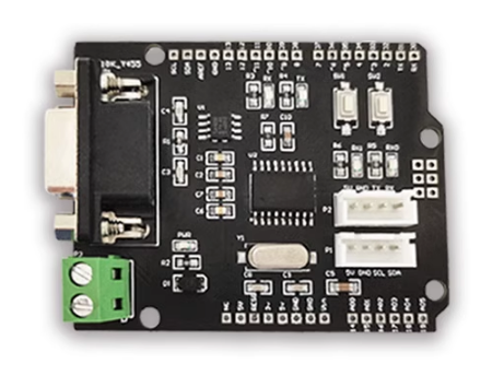
LC CAN module has become the preferred choice in embedded system design due to its excellent performance and flexibility
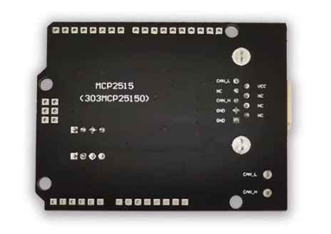
It adopts MCP2515 CAN controller and NXP CAN protocol chip, and the combination of the two ensures the efficiency and stability of the module in CAN communication protocol
By seamlessly integrating with Arduino, developers can quickly build powerful devices such as CAN protocol analyzers and data transceivers
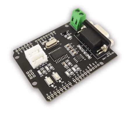
The module design is well considered, with two reserved button interfaces, providing convenience for user operation
In addition, it is equipped with IIC interface and serial port, further expanding the module's connectivity and application scenarios
Whether in the fields of industrial automation, automotive electronics, or smart homes, this CAN module can help your project quickly integrate and develop CAN communication with its efficient and reliable performance
View
Front view
Side view
Reverse image
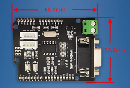
Introduction and Explanation
Board size: 68.5 * 53.5mm/28g
Functional Features
- Perfectly compatible with Arduino UNO, enabling developers to easily integrate with Arduino UNO. This design not only simplifies the process of hardware connection, but also greatly expands the functional boundaries of Arduino
- The module is equipped with a serial port indicator light, which visually displays the communication status of the data transmission and reception process, ensuring transparency and real-time operation
- CAN data can be input through a 9-pin serial port or wiring terminal, which can meet the needs of different scenarios
Instructions for use
Refer to the schematic diagram and use the PSI interface to communicate with Arduino. You can search for a suitable Arduino library to drive MCP2515. The reference program uses acan2515
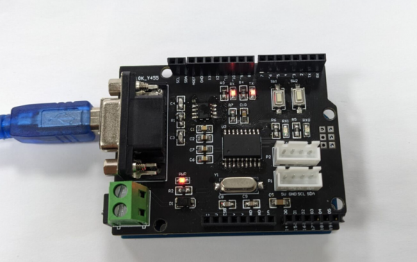
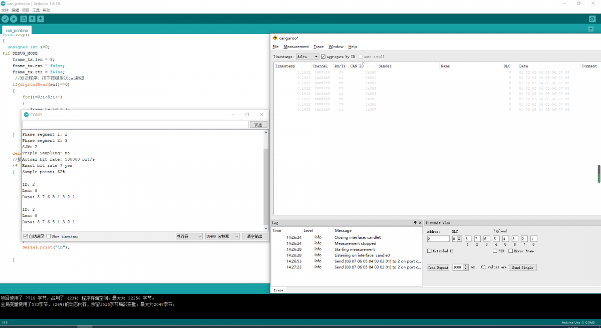
Connect as shown in the diagram, power on to burn the reference program, press the SW1 button, and the CAN module will generate data
It is recommended to use it in conjunction with a USB to CAN analyzer, as the data generated can be seen on the upper computer
Send data from USB to CAN host computer to Arduino, and Arduino can print out the received CAN data
Download User Manual
For more usage information, please refer toBaidu Cloud Drive Extraction code: 0170
