Difference between revisions of "LC-MK-ESP-CK-1"
(Created page with "== '''Product name''' == ESP8266 0.96 inch OLED clock module perpetual calendar ESP-12F LCD development board<br> == '''Overview''' == Elsay ESP8266 0.96-inch OLED clock m...") |
(→Overview) |
||
| (One intermediate revision by the same user not shown) | |||
| Line 6: | Line 6: | ||
== '''Overview''' == | == '''Overview''' == | ||
| − | + | LC ESP8266 0.96-inch OLED clock module integrates ESP-12F module, 0.96-inch OLED display, RTC perpetual calendar clock chip and CR1220 battery, provides supporting configuration software, and can be used to DIY your own LCD WiFi clock/weather station. Lead out the ESP8266 programming port, and interested friends can carry out secondary development on it.<br> | |
| − | |||
| − | |||
| − | |||
== '''Function''' == | == '''Function''' == | ||
| Line 31: | Line 28: | ||
| − | == '''Introduction'' == | + | == '''Introduction''' == |
1. Board size: 29*29mm Weight: 13g<br> | 1. Board size: 29*29mm Weight: 13g<br> | ||
[[File:MK-ESP-CK-1-1.png]]<br> | [[File:MK-ESP-CK-1-1.png]]<br> | ||
| Line 44: | Line 41: | ||
6. UART program download interface: IO0 and GND are shorted when downloading, 3V3, TXD, RXD, and GND are respectively connected to 3V3, RXD, TXD, and GND of an external TTL serial port module (such as FT232 module), and disconnect IO0 and GND after the download is completed Link<br> | 6. UART program download interface: IO0 and GND are shorted when downloading, 3V3, TXD, RXD, and GND are respectively connected to 3V3, RXD, TXD, and GND of an external TTL serial port module (such as FT232 module), and disconnect IO0 and GND after the download is completed Link<br> | ||
7. OLED interface: respectively SDA, SCL, GND, 3V3<br> | 7. OLED interface: respectively SDA, SCL, GND, 3V3<br> | ||
| − | |||
| − | |||
| − | |||
== '''Hardware connection''' == | == '''Hardware connection''' == | ||
Latest revision as of 15:48, 12 March 2024
Product name
ESP8266 0.96 inch OLED clock module perpetual calendar ESP-12F LCD development board
Overview
LC ESP8266 0.96-inch OLED clock module integrates ESP-12F module, 0.96-inch OLED display, RTC perpetual calendar clock chip and CR1220 battery, provides supporting configuration software, and can be used to DIY your own LCD WiFi clock/weather station. Lead out the ESP8266 programming port, and interested friends can carry out secondary development on it.
Function
- Onboard mature and stable ESP-12F WiFi module, large capacity 4M Byte Flash
- Onboard I2C communication interface 0.96 inch OLED display
- Provide reference codes and documents for OLED display 51, STM32 and other environments
- Onboard PCF8563T clock circuit, even if the power is off, it can keep time normally
- Reserve ESP8266 UART interface, support secondary development and write your own firmware
- Provide ESP8266 factory firmware, schematic diagram
- Power supply mode: Micro USB 5V power supply
- Double-layer structure design, small size and good appearance, the best choice for DIY WiFi clock
Introduction
1. Board size: 29*29mm Weight: 13g
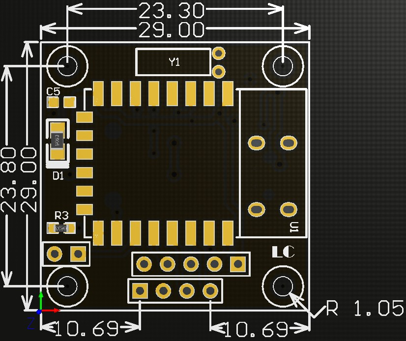
2.Introduce for interface
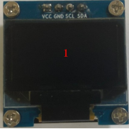
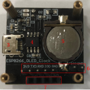
1. 0.96-inch OLED display: the drive IC is SSD1306
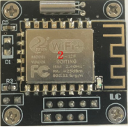
2. ESP-12F WiFi module: Flash capacity is 4MByte
3. Micro USB 5V power supply interface
4. PCF8563T clock chip
5. CR1220 button battery: supply power to the clock circuit after power failure
6. UART program download interface: IO0 and GND are shorted when downloading, 3V3, TXD, RXD, and GND are respectively connected to 3V3, RXD, TXD, and GND of an external TTL serial port module (such as FT232 module), and disconnect IO0 and GND after the download is completed Link
7. OLED interface: respectively SDA, SCL, GND, 3V3
Hardware connection
The firmware of the module has been burned before leaving the factory. Customers need to connect it to the router (2.4GHz WiFi) before using it, and then set the city, so as to obtain the correct time and weather information. The steps are as follows:
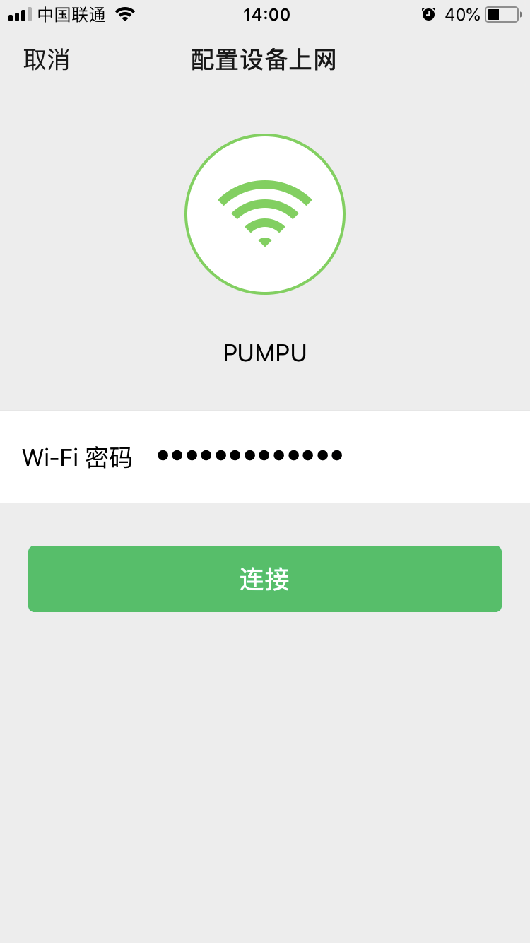
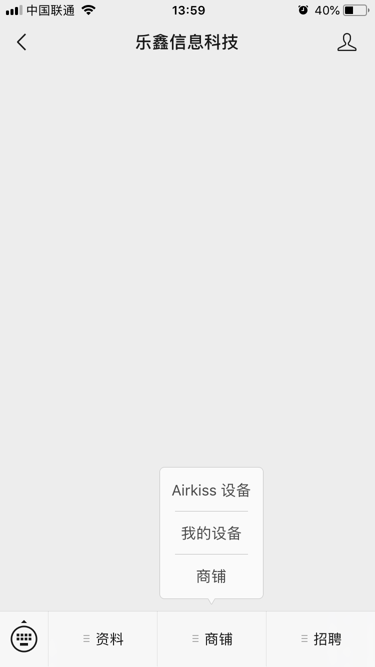
1. The WiFi clock module is powered by USB, and then the Android/iPhone mobile phone is connected to the WiFi first, follow the official account of "Espressif Information Technology" on WeChat, and then click on the store--Airkiss device, enter the WiFi password, and click "Connect"
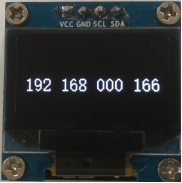
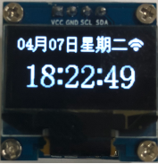
2. Wait for about 15 seconds until the WiFi icon appears in the upper right corner of the module display and the IP address appears, indicating that it has successfully connected to the router, and then refreshes the accurate Beijing time and date, as shown in the figure below:
3. Factory firmware programming
For secondary development customers who want to reprogram the factory firmware, they can follow the steps below:
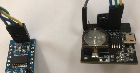
(1)Connect the IO0 and GND pins with a jumper cap/DuPont line, prepare a TTL serial port module (for example: FT232) and plug it into the computer USB. The connection method between the serial port module and the development board is as follows:
| TTL serial port module | WiFi clock module |
| GND | GND |
| TX | RX |
| RX | TX |
| 3.3V | 3V3 |
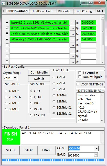
(2)Use the firmware programming software FLASH_DOWNLOAD_TOOLS_V3.6.4 to open the firmware, set the programming address, port number and other parameters, and click START. After the programming is completed, the connection between IO0 and GND must be disconnected to run the program, as follows:
Kind tips:
1. The above address for programming is applicable to the factory firmware, and customers for secondary development, please choose the address according to the actual situation
2. When configuring the network for the clock module, the router, clock module, and mobile phone should be as close as possible
3. During the network distribution process, the mobile phone may prompt "failed to configure wifi", don't worry about it, as long as the clock module can display the WiFi icon and IP address, it means that the network distribution is successful
4. Only the factory firmware is provided, and the ESP8266 source code under Eclipse is not provided!
