Difference between revisions of "LC-EM-1114"
(Created page with "==Product Name== Electronic switch NMOS driver module DC low voltage high current switch isolated input ==About== LC electronic switches use high current NMOS transistors fo...") |
|||
| Line 4: | Line 4: | ||
==About== | ==About== | ||
| − | LC electronic switches use high current NMOS transistors for circuit switching | + | LC electronic switches use high current NMOS transistors for circuit switching<br> |
| − | Using optocoupler isolation input method to protect the safety of the control end | + | Using optocoupler isolation input method to protect the safety of the control end<br> |
| − | Can be used in low-frequency, low-voltage, and high current applications, such as DC brushed motors, heaters, etc | + | Can be used in low-frequency, low-voltage, and high current applications, such as DC brushed motors, heaters, etc<br> |
Latest revision as of 13:28, 24 July 2024
Contents
Product Name
Electronic switch NMOS driver module DC low voltage high current switch isolated input
About
LC electronic switches use high current NMOS transistors for circuit switching
Using optocoupler isolation input method to protect the safety of the control end
Can be used in low-frequency, low-voltage, and high current applications, such as DC brushed motors, heaters, etc
View
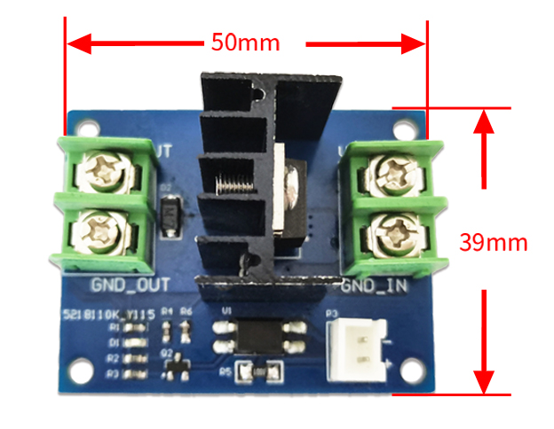
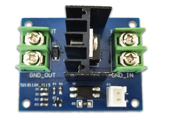
Front view
Side view
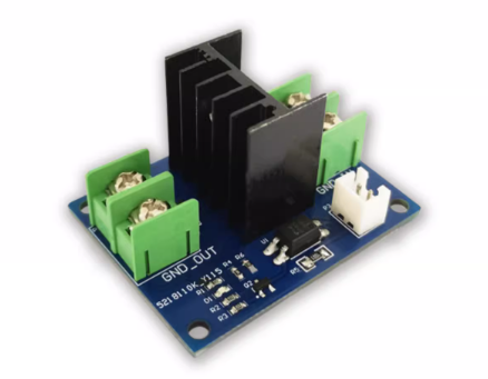
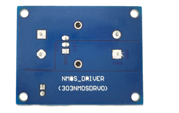
Reverse image
Introduction and Explanation
Functional Features
- Input power supply voltage 12~40V
- The input voltage of the control terminal is 3.3~24V, suitable for control methods such as single-chip microcontrollers or PLCs
- The output current can reach 10A
- Can be used in low-frequency, low-voltage, and high current applications, such as DC brushed motors, heaters, etc
Instructions for use
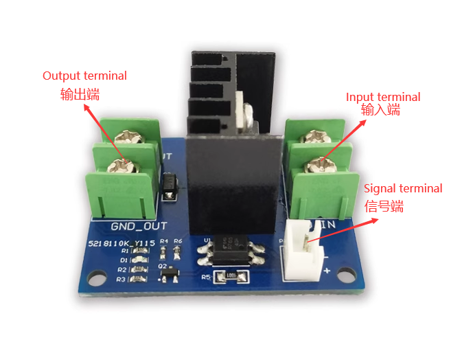
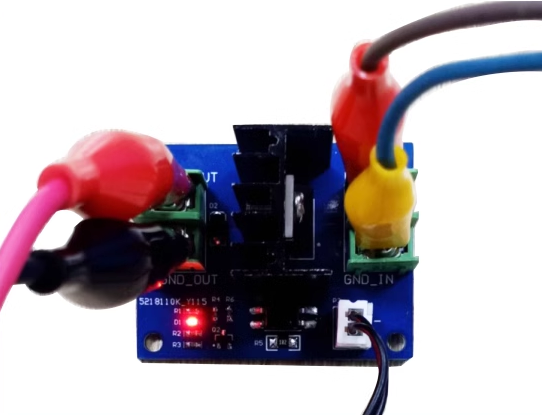
1. Connect the output load on the left side, with positive upper and negative lower
2. Connect the input power supply on the right side, with a positive top and negative bottom, and a power range of 12-40V
3. XH2.54 socket is connected to the control signal, with upper negative and lower positive, and 3.3V~24V open
4. Connect the power supply and control signal. When the switch is turned on, the red LED will light up
Download User Manual
For more usage information, please refer toBaidu Cloud Drive Extraction code: 7kqa
