Difference between revisions of "LC-IOT-1023"
| Line 57: | Line 57: | ||
The SIM card must be connected before powering on, and the board will automatically connect to the internet and turn on the MOS transistor<br> | The SIM card must be connected before powering on, and the board will automatically connect to the internet and turn on the MOS transistor<br> | ||
[[Image:LC-IOT-1023-08.png|400px|]]<br><br> | [[Image:LC-IOT-1023-08.png|400px|]]<br><br> | ||
| + | |||
| + | |||
| + | ==User Manual Download== | ||
| + | For more product information, please refer to[https://pan.baidu.com/s/1Zn662HDtELHrzhhOtt4-ow?pwd=vf8q Baidu Cloud Drive] Extraction code: vf8q | ||
Latest revision as of 09:16, 9 August 2024
Contents
Product Name
STM32 4G Networking MOSFET Switch Development Board Air780e Module
Regarding LC-IOT-1023
Air780E is an LTE Cat.1 bis communication module launched by Luat Communication. It is a 4G full network and can adapt to different operators and products.
By default, it uses AT firmware to communicate with STM32 through serial port and uses AT commands for networking data transmission and reception
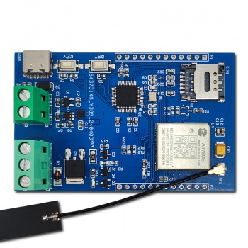
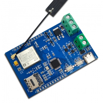
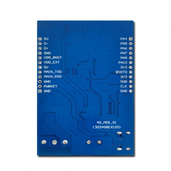
LC-IOT-1023 View
LC-IOT-1023 Front View
LC-IOT-1023 Side View
LC-IOT-1023 reverse view
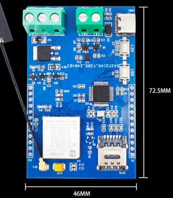
Introduction and Explanation
Interface Description
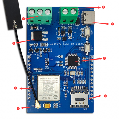
① Output terminal
② Drive circuit
③ AIR780E
④ Antenna pedestal
⑤ SIM card holder
⑥ STM32 microcontroller
⑦ Power supply USB
⑧ Power supply terminal
Functional Features
- Onboard AIR780E module, 4G full network, low power consumption, sleep power consumption as low as 600uA
- Flip up nano SIM card holder, easy to install and remove
- The onboard STM32F103C6T6 chip can be developed based on AT instructions using a microcontroller, or directly based on AIR780E
- The output MOS transistor adopts NCE6050KA, with a maximum withstand voltage of 60V and a maximum current of 50A (data manual value)
- Onboard reset button and user button, users can develop their own desired functions
- Introduce commonly used IO ports for microcontrollers and AIR780E for easy debugging
- Use KF128 2P terminal for 5V power supply or use Type-C power supply
- Use KF128 3P terminal as MOS transistor output
- Onboard blue AIR780E network status indicator light
Instructions for use
MOS transistor output wiring method:
VCC: Connect to load for power supply
MOT+: Connected to the positive pole of the load, MOT+is connected to VCC
MOT -: Connect the negative pole of the load
GND: The power supply GND of the load needs to be connected to the GND of the control terminal and connected to the board
+5V: The control terminal is powered by+5V and is responsible for supplying power to microcontrollers and other devices. Overvoltage should not be exceeded
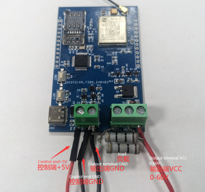
The default program is STM32 to send AT commands requesting Air780e to connect to the network. If the connection is successful, the MOS transistor will be turned on
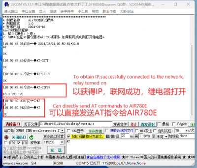
Prepare a USB to serial port connection to the board, connect PA9 to RX, PA10 to TX, and GND to GND
The SIM card must be connected before powering on, and the board will automatically connect to the internet and turn on the MOS transistor
User Manual Download
For more product information, please refer toBaidu Cloud Drive Extraction code: vf8q
