LC-IOT-1025
Contents
Product Name
LC STM32 4G Dual Relay Development Board AIR780E-4G module STM32 development board Dual 5V relay
About
The Air780e module of the LC STM32 4G dual relay development board uses STM32F103C6T6 as the main control chip, and is equipped with the Air780E LTE Cat.
1 bis communication module launched by Luat Communication. It is a 4G full network communication module.Can adapt to different operators and products,
defaults to using AT firmware, communicates with STM32 through serial port, and uses AT commands for networking data transmission and reception functions;
When the dual relay is powered on and connected to the grid, it will open immediately.The product supports Type_C port+KF128 terminal power supply mode,
and commonly used pins are basically fully led out, which is convenient for secondary development.
View
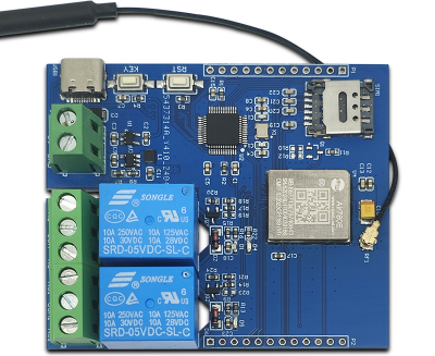
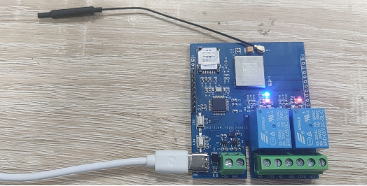
Front view
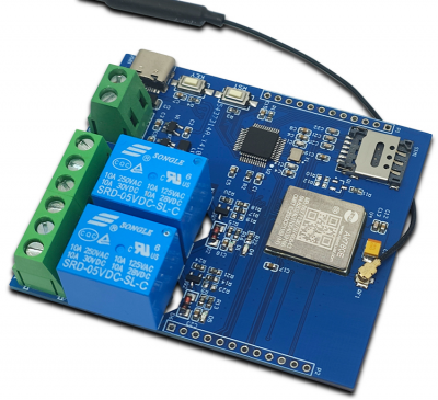
Side view
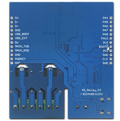
Reverse image
Introduction and Explanation
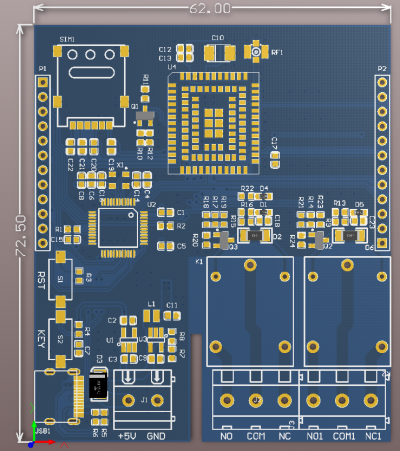
Size: 62 * 72.5mm/45 g
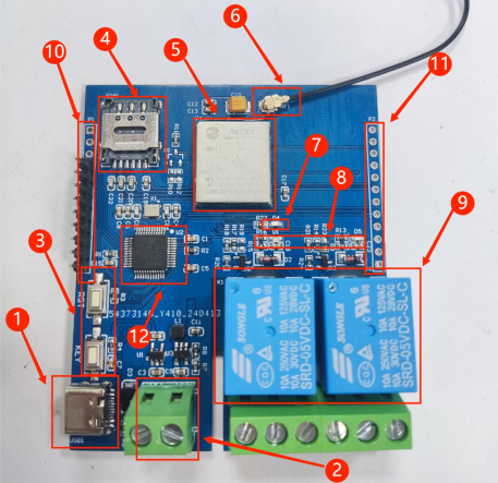
Interface Introduction
1. Type_C port: power supply+USB interface
2. KF128 power supply terminal: 5V power supply
3. Key: RST reset key+KEY key (PB12)
4. Nano SIM card holder: When inserting the card with internet access, the power on relay will open
5. Air780e module
6. Antenna
7. Blue network status indicator light: It will light up repeatedly after power on, and will accelerate to turn on and off when there is a network
8. Relay status indicator light
9. Dual 5V relay
10. Common IO pins for STM32
11. Common IO pins for Air780e
12.MCU:STM32F103C6T6(LQFP-48)
Functional Features
- Using the mature and stable STM32F103 series 32-bit microcontroller, users can develop based on AT instructions or directly based on AIR780E;
- Onboard AIR780E module, low power consumption, sleep power consumption as low as 600uA;
- Flip up nano SIM card holder, easy to install and remove;
- Onboard blue AIR780E network status indicator light;
- Onboard reset button and user button, users can develop their own desired functions;
- Support Type-C power supply+KF128 terminal 5V power supply;
- The commonly used IO ports of the microcontroller and AIR780E are mostly fully connected.
Module usage instructions
1. Program burning - USRT: Prepare a USB to TTL module (such as CH340) and plug it into the computer's USB port. The connection method to the module is as follows:
| TTL serial port module | 4G development board |
| GND | GND |
| TX | RX |
| RX | TX |
| 3.3V | 3.3V |
Then plug in the jumper cap between the BOOT0 pin and 3.3V to burn the firmware
2. Program burning - SWD: Prepare a Link debugger (ST Link, J-Link, etc.) and plug it into the USB port of the computer. The Link and module connection method is as follows:
| Link debugger | 4G development board |
| GND | GND |
| SWCLK | DCK |
| SWDIO | DIO |
| 3.3V | 3.3V |
Then select the firmware for burning
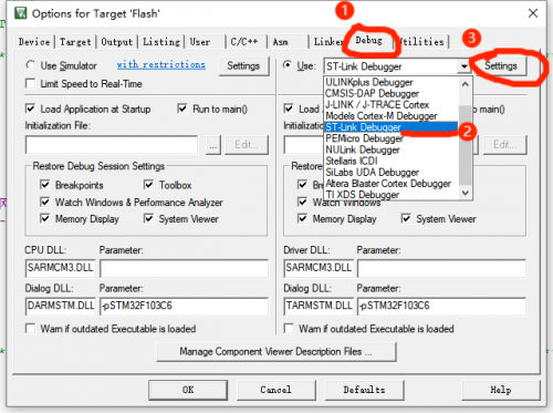
3. Debug: After connecting the Link burner in the above way, click the 'Debug' button of the compiled software, select 'ST Link', and then click Settings
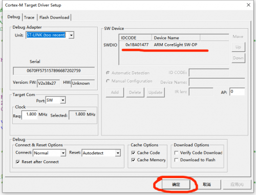
If the SW Device displays a device, it means that the debugger has successfully recognized it. Set the parameters according to the following figure and click OK
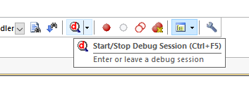
Then press Ctrl+F5 or click the debug button to start debugging:
4. Module Function Testing
Plug in an available SIM card and then power it on. The network indicator light on the development board will turn on and off for a period of time,
and the speed will increase. At the same time, the relay will turn on
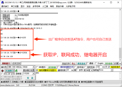
The default program is STM32 to send AT commands requesting Air780e to connect to the network. If the connection is successful, the relay will be turned on
If the relay does not respond, it may be a networking failure. At this time, use a TTL serial port module to connect to the board,
connect PA9 to RX, PA10 to TX, and GND to GND. Then open the serial port debugger, select the corresponding port and baud rate,
and open the serial port.Press the reset button to check the printed window data. If it displays as shown in the figure below,
it means there is no problem with networking. If networking fails, please try changing the card and trying again
User Manual Download
For more product information, please refer toBaidu Netdisk Extraction code: vjtt
