LC-WF-12-1
Contents
Product Name
DC powered ESP-12F single MOS switch module ESP12F development board ESP8266MOD secondary development
About
The LC DC powered ESP12F single MOS switch module is equipped with ESP-12F (ESP8266MOD) module, with all I/O ports leading out, supporting DC5-80V power supply mode+Micro-USB port power supply. Suitable for ESP-12F secondary development learning, smart home wireless control and other occasions
View
Front view
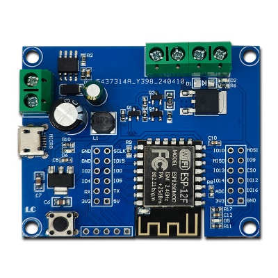
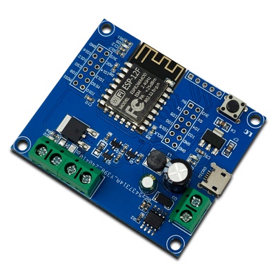
Side view
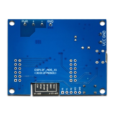
Reverse image
Introduction and Explanation
Board size: 48mm * 59mm/18g
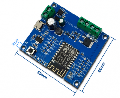
Interface Introduction
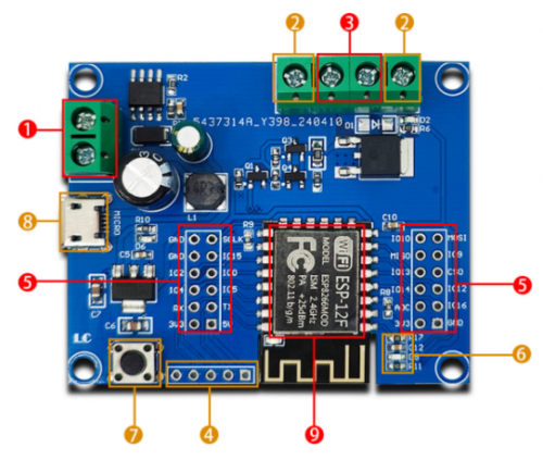
1. Power supply port: 5-80V power supply
2. Output power supply port: Supply voltage below DC60V
3. Output load port: Provides power to the load circuit
4. Serial port burning pin
5. All IO pins
6. Programmable indicator light: IO16 pin control
7. RST reset key (press this key when pulling down the IO0 pin to enter burning mode)
8. Micro-USB power supply port
9. MCU: ESP-12F (ESP8266MOD) module
Functional Features
- On board mature and stable ESP-12F (ESP8266MOD) module, with a large capacity of 32Mbit SPI Flash
- The I/O ports and UART program download ports of the ESP-12F module are all exported for easy secondary development
- On board Micro-USB port+DC-5-80V to 5V power supply circuit (recommended to supply DC-12V)
- Onboard RST reset key
- ESP-12F supports Arduino IDE compilation tool and provides reference programs for Arduino development environment
- N-channel MOS transistor with onboard leakage source voltage of 60V, suitable for controlling loads with "control operating voltage" within DC60V
Program Download
1. Pull down the IO0 pin and press the key at the same time to enter the burning mode. Refer to the module specification book:
| mode | CH_PD(EN) | RST | GPI015 | GPI00 | GPI02 | TXD0 |
| Download mode | 1 | 1 | 0 | 0 | 1 | 1 |
| Operation mode | 1 | 1 | 0 | 1 | 1 | 1 |
Note: Some pins have internal pull-up resistors, please refer to the schematic diagram for details.
Prepare a TTL serial port module (such as CH340) and plug it into the computer USB. The connection method between the serial port module and the development board is as follows:
| TTL serial port module | ESP32 development board |
| GND | GND |
| TX | RX |
| RX | TX |
| 3.3V | 3.3V |
2. Open the Arduino IDE compilation tool, click on "Tools" in the menu bar, select "Development Board", and choose "ESP-12F Module" as the development board
3. Open the program you want to download, click on "Tools" in the menu bar, select "Port" and choose the correct port number
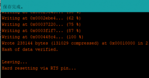
4. After clicking "Upload", the program will automatically compile and download to the development board, as shown below:
5. Finally, power on the development board again or press the reset key to run the program
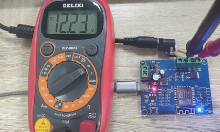
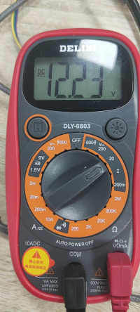
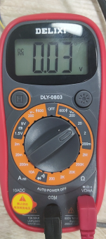
6. Supply power to the output terminal power supply port (theoretically up to 60V DC, here testing uses 12V DC power supply), and then use a multimeter to measure the voltage value of the output terminal load port. The multimeter values in the open and closed states of the MOS transistor are shown in the following figure:
Open:
Close:
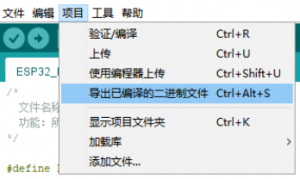
7. When using tools to burn programs, after compiling, click on the project - Export Binary Files, and then enter the burning tool to burn. You can refer to the following article:[1]
User Manual Download
For more product information, please refer toBaidu Cloud Drive Extraction code: e9gu