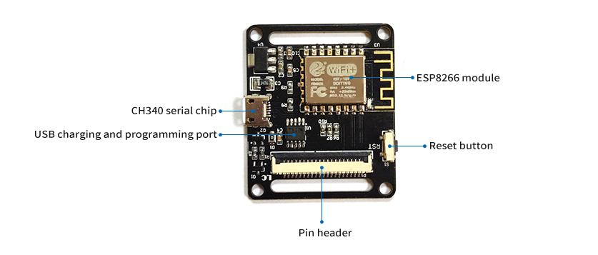
LC-MK-ESP-WT
Product name
ESP8266 watch programmable development board wifi watch ESP watch ESP development board wifi development board
Overview
LC ESP8266 watch development board, using ESP-12F module, the powerful 8266 chip can use your imagination to develop the functions you want, onboard 3.7v lithium battery and charging circuit, the appearance is watch-shaped and has a strap, you can wear it In the hand, adding an oled display is more intuitive and beautiful.
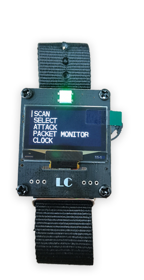
Function
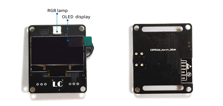
A 1.3-inch OLED core on board is SH1106, an RGB light and a three-way wave switch, powered by a 3.7v polymer lithium battery, and the USB port can be used as a programming port or a charging port; the compact size is matched with a watch It is very convenient to carry on the hand, control the device anytime and anywhere.
Introduction
Board size: 45*38mm
Height 18mm after installation
Weight: 30g
Explanation of physical diagram of board function:
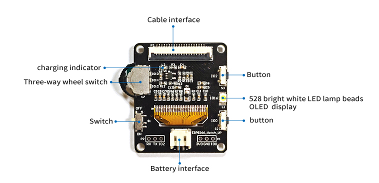
Hardware connection
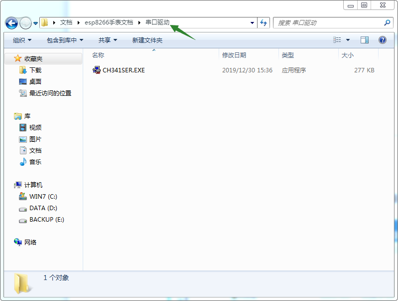
Connect the USB cable and connect to the computer, open the serial port driver folder, and install the CH340 driver. If you have installed and tested it before, you don’t need to install it. If you can’t use it, the driver version may be too low and you need to reinstall it.
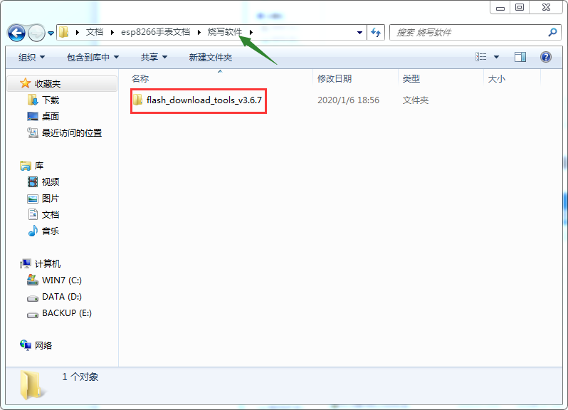
Open the flash_download_tools_v3.6.7 of the programming software, select ESP8266
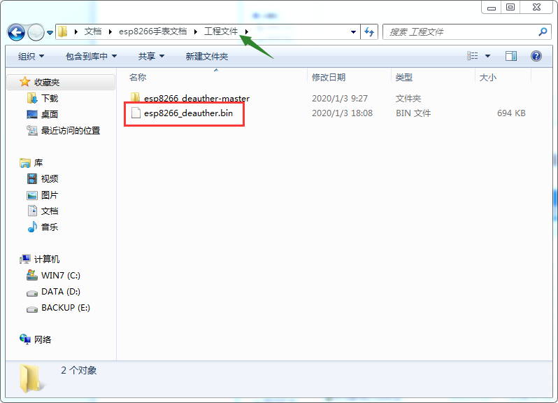
Then select the esp8266_deauther.bin of the project file and burn it into the ESP8266 watch. The burning configuration is as shown in the figure:
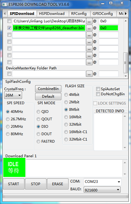
Note: When programming the ESP8266 watch development board, the upper and lower boards need to be connected with the cable and the switch should be turned on to be able to program normally!
