LC-WF-3-1
Contents
Product name
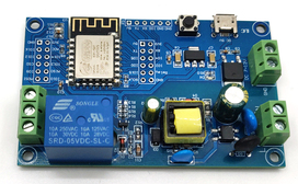
AC/DC power supply ESP-12Fdevelopment board WIFI 1-way relay module secondary development WIFI smart switch.
Overview
LC ESP8266 1-way relay development board is equipped with ESP-12F WiFi module, all I/O ports are drawn out, and supports AC90-250V/DC7-12V/USB 5V and other power supply methods.
Provide Arduino development environment reference code, suitable for ESP8266 secondary development learning, smart home wireless control and other occasions.

Feature
- Onboard mature and stable ESP-12F WiFi module, large capacity 4M Byte Flash
- The I/O port of the WiFi module and the UART program download port are all exported to facilitate secondary development
- Onboard AC-DC switching power supply module, power supply mode supports AC90-250V/DC7-12V/USB5V
- Onboard WiFi module RST reset button
- ESP-12F supports the use of development tools such as Eclipse/Arduino IDE, and provides reference programs in the Arduino development environment
- Onboard 1-way 5V relay, output switching signal, suitable for controlling loads with working voltage within AC 250V/DC30V
- Onboard power indicator, 1 programmable LED and relay indicator
Description for interface
| Logo | Description |
| L, N | AC90-250V power supply |
| VCC, GND | DC7-12V power supply |
| Micro USB | DC5V USB power supply |
| 6X6mm button | ESP8266 reset button |
| UART program download port | GND, RX, TX, 5V of ESP8266 are respectively connected to GND, TX, RX, 5V of external TTL serial port module; When downloading, IO0 needs to be connected to GND. After the download is complete, disconnect the connection between IO0 and GND |
| GPIO header port | GND: power ground Relay: relay drive port, IO5 drive is used by default, if you want to use other I/O ports to drive the relay, you can remove R14, and then connect the I/O pin of the drive relay to this Relay pin |
| D6 | Power switch indicator light; |
| D5 | Programmable LED; |
| D2 | Relay switch indicator light; |
| NC | Normally closed terminal, before the relay pulls in, it is shorted with COM, and after the pull-in, it is suspended; |
| NO | Normally open, suspended in the air before the relay pulls in, and short-circuited with COM after the pull-in; |
| COM | public port; |
Description for connection
Arduino development environment setup:
ESP8266 supports Eclipse/Arduino IDE and other development tools. It is relatively simple to use Arduino. The following is how to build the Arduino development environment:
1. Install Arduino IDE 1.8.9 or the latest version;
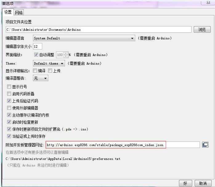
2. Open the Arduino IDE, click File--Preferences in the menu bar, enter the preferences and click Add Network in the "Additional Development Board Manager URL".
http://arduino.esp8266.com/stable/package_esp8266com_index.json

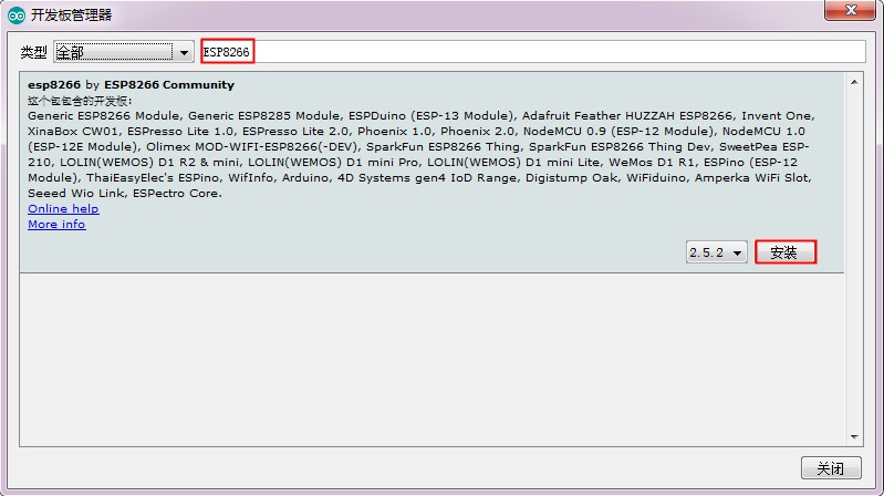
3. Click Tools--Development Board--Development Board Manager in the menu bar, and then search for "ESP8266" to install Arduino's support package for ESP8266 2.5.2 or the latest version;

Note: Since the download URL is from a foreign country, the access speed is relatively slow, and there may be download errors. Just try a few more times when the network is good.
Program download:
1. Use jumper caps to connect IO0 and GND pins, prepare a TTL serial port module (for example: FT232) and plug it into the computer USB; GND, RX, TX, 3.3V are respectively connected to GND, TX, RX, 3.3V of the external TTL serial port module V;
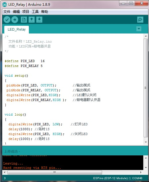
2. Click Tools--Development Board in the menu bar, and select the development board as ESPino (ESP-12 module);
3. Open the program to be downloaded, click Tools--Port in the menu bar and select the correct port number;
4. After clicking "Upload", the program will be automatically compiled and downloaded to the development board;

5. Finally, disconnect the connection between IO0 and GND, power on the development board again or press the reset button to run the program