LC-WF-5-1
Contents
Product name
Single-channel ESP8266 network remote relay module 220V mobile app control wifi smart home switch
About LC-WF-5-1
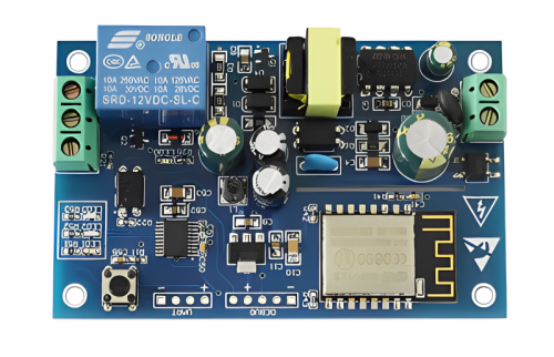
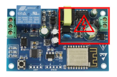
LC 220V single-channel WIFI relay module uses ESP8266 as the WIFI module, combined with a mature and stable 8-bit MCU, and a professional switching power supply circuit
Mains power can be directly used as the power input, and only a simple configuration process can be used to achieve wireless control of the relay in the local area network using the mobile phone APP.
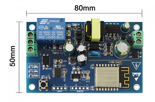
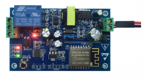
LC-WF-5-1 view
Introduction instructions
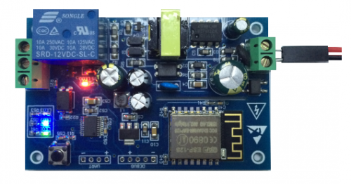
Hardware introduction
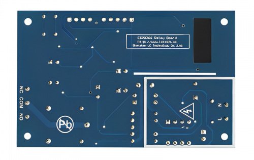
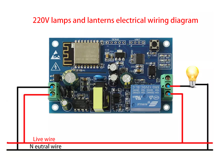
1.L、N:AC mains input
2.Buttons: Mode switching (default is mode 1) + factory reset button, short press to switch modes, long press for more than 3S to restore factory settings
3.LED0 (red light): relay working indicator light, lights up when turned on
4.LED3 (red light): Mode 1 indicator light
5.LED2 (blue light): Mode 2 indicator light
6.LED1 (green light): Working status indicator light, described as follows:
(1) When it turns off, it means that it is self-configuring or has lost connection with the router.
(2) When it flashes quickly for 0.5S, it means waiting for the mobile APP to configure the WIFI account and password for the ESP8266 module.
(3) When it flashes slowly for 2S, it means that the configuration is completed and waiting to establish a TCP connection with the mobile phone.
(4) When it is always on, it means the TCP connection has been successfully established with the mobile phone.
7.COM public terminal:
NC: Normally closed terminal, short-circuited to COM before the relay closes, and left floating after closing
NO: Normally open terminal, the relay is suspended before closing, and short-circuited with COM after closing
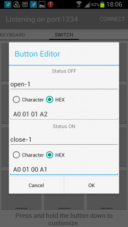
8.Relay control instructions (hexadecimal hex format):
Open relay: A0 01 01 A2
Close relay: A0 01 00 A1
Function features
- Onboard high-performance microprocessor and ESP8266WIFI module
- Mode has 2 working modes:
(1)Mode 1: The mobile phone is directly mounted on the WIFI module
(2)Mode 2: The mobile phone and WIFI module are mounted on the router at the same time
- Transmission distance:
(1) In an open environment, the maximum stable transmission distance is 100m when the mobile phone is mounted on the WIFI module
(2) When the WIFI module and the mobile phone are installed on the router at the same time, the transmission distance depends on the signal strength of the router
- Using Smartconfig technology, you can complete the configuration of the ESP8266 WIFI module account and password on the mobile APP. The configured account and password have a power-off memory function
- It adopts ST original switching power supply IC, which can be directly connected to the mains power, and has a wide voltage input range: AC85V-264V, and stable DC voltage output to ensure the stable operation of the control part
- Onboard Songle original relay, parameters: 12V, 10A/250V AC 10A/30V DC relay, can continuously pull in 100,000 times, with diode overflow protection, short response time
- Made of PCB sheets and processes that comply with RoHS regulations, a good choice for foreign trade
- Onboard relay, mode selection, real-time working status indicator light
- Reserved UART debugging interface and MCU program download interface
Use description
1.Tool software
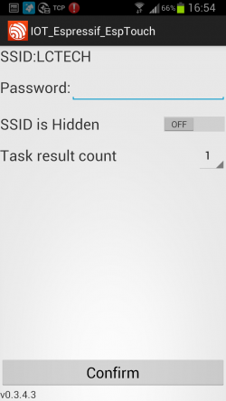
(1) EspTouch_Demo software is used to configure the WIFI account and password for the ESP8266 module when using working mode 2 for the first time.

(2) EasyTCP_20 software, used to send relay control instructions

2.Preparation
(1) L and N are connected to 220V mains power
(2) Install the APP "EspTouch_Demo" on the Android phone, which is used to configure the WIFI account and password for the ESP8266 module when using working mode 2 for the first time.
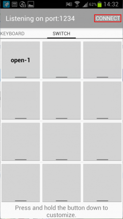
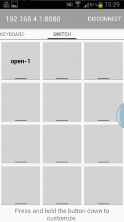
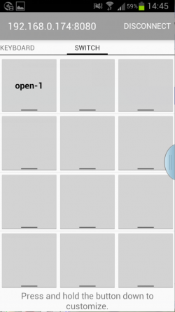
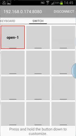
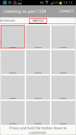
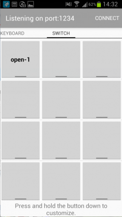
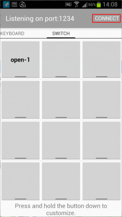
(3) Install the APP "EspTCP_20" on the Android mobile phone, a TCP transmission tool, used to send relay control instructions, click "SWITCH"
Then long press the gray square in the interface to enter the name and content of the relay control command (the command format is HEX format)
3.Use description
(1) Working mode 1 (the mobile phone is equipped with the ESP8266 module)
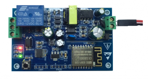
① After the module is powered on, the green light changes from off to slow flashing for 2 seconds after about 4 seconds, indicating that the configuration is completed, as follows:
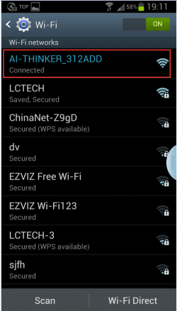
②The mobile phone is connected to the AP hotspot signal sent by the ESP8266 module
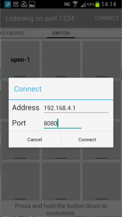
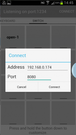
③Open the "EasyTCP_20" APP, click "CONNECT", enter the IP address: 192.168.4.1 and port number 8080, and then click "Connect"
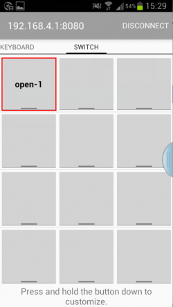
After the connection is successful, the green light will flash slowly from 2S to steady on. Click the gray square to send instructions to control the switch of the relay.
(2) Working mode 2 (mobile phone and ESP8266 module are mounted on the router at the same time)
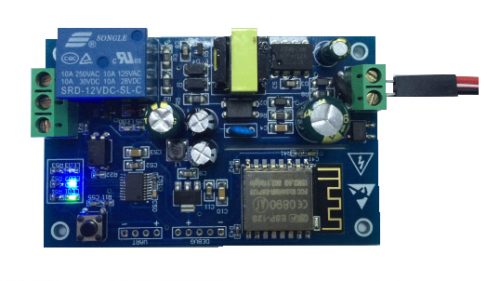
① After the mode is powered on, wait for the green light to flash slowly and then press the button to switch to mode 2. The blue light will light up. After about 1 minute, the green light will turn from off to 0.5S fast flashing,It means waiting for the "EspTouch_Demo" APP to configure the WIFI account and password for it.
②At this time, connect the mobile phone to the router first, open the "EspTouch_Demo" APP, enter the router password, and click "Confirm"
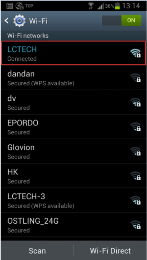
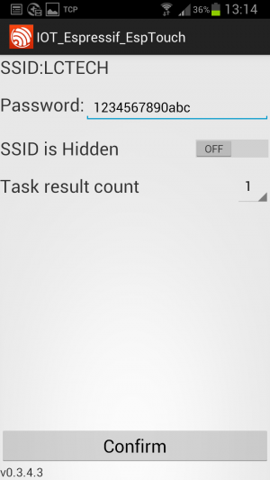
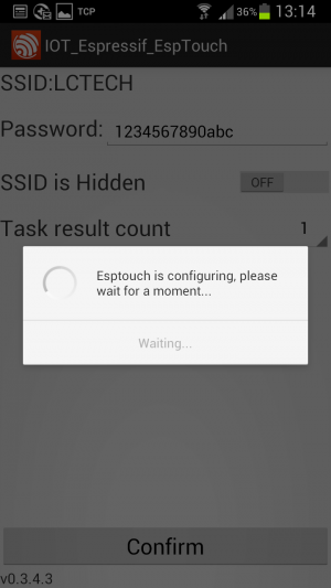
③ Wait for the configuration to be successful. When the IP address of ESP8266 (such as 192.168.0.174) appears on the APP interface, it means that the ESP8266 module has successfully connected to the router and automatically memorized the account and password,The next time you enter mode 2, it will automatically connect (it will take about 20-60 seconds to connect)
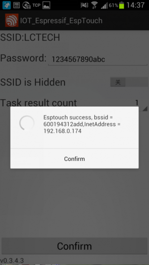
It should be noted that the IP address 192.168.0.174 is dynamically assigned to the ESP8266 module by the router. The address may change after the next reconnection,You can check the real-time IP address of the ESP8266 module in the router's device list.
④Open the "EasyTCP_20" APP, click "CONNECT", enter the IP address of the ESP8266 module: 192.168.0.174 and port number 8080, and then click "Connect"
After the connection is successful, the green light will flash slowly for 2 seconds and turn solid. Click the gray square to send instructions to control the switch of the relay.
1.The waiting time to configure the WIFI password for the first time will be slightly longer (about 1 minute). After the configuration is completed, it will only take 20 seconds to automatically connect the next time you turn on the computer.
2.If you want to replace the router, you can power off and restart or press and hold the button for more than 3 seconds (long pressing the button will clear the previously memorized WIFI account and password),and reconfigure the WIFI account and password for ESP8266 in mode 2.
3.When the signal of the router memorized by ESP8266 is very weak or is not in the service area, causing the connection to be interrupted, the green light will go out and the connection will be automatically attempted. During this process, the buttons will be in an invalid state. When the street light flashes slowly for 2S, the connection has been restored.
4.In Mode 1 and Mode 2, the button is only available when the green light flashes slowly for 2 seconds or is always on. In other cases, the button is invalid due to internal self-configuration of the chip or waiting for the configuration process.
5.ESP8266 has a timeout mechanism. If there is no data exchange between the mobile phone and ESP8266 for more than 6 minutes, the TCP connection will be automatically disconnected. At this time, click "CONNECT" in the upper right corner of the "EasyTCP_20" APP to re-establish the connection.
Download LC-WF-5-1 user manual
For more information on the use of LC-WF-5-1, please view https://pan.baidu.com/s/1qdIPYycwFGt5qgmrM7Bvjw
