LC-EM-1160
Contents
Product Name
ADS1256 24 bit 8-channel ADC AD module high-precision ADC data acquisition card
Overview
The LC ADS1256 8-channel 24 bit ADC module is equipped with TI ADS1256IDB Micro power consumption, high-precision ADC chip, and 2.5V reference voltage source. It has SPI interface communication and a data output rate of up to 30ksps, supporting single ended and differential inputs.
View
Front view
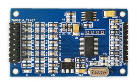
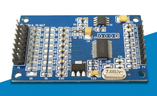
Side view
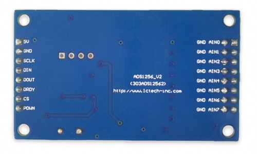
Reverse image
Product parameters
Onboard chip:Onboard high-precision TI ADS1256IDB ADC chip and ADR03 2.5V power reference chip
Data output rate:The data output rate can reach 30ksps, with a low nonlinearity of ± 0.0010%
Single ended/differential input:The module can be configured with 8 single ended inputs or 4 differential inputs
Measure analog voltage:Suitable for measuring analog voltages up to 3V
Working voltage:5V
Introduction and Explanation
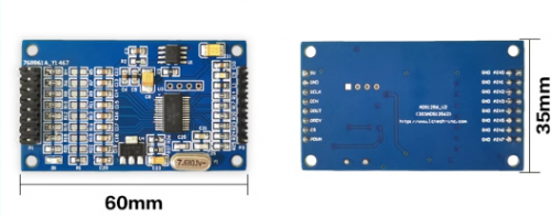
Board size: 35 * 60mm
Board Function Description:
1. Interface Description:
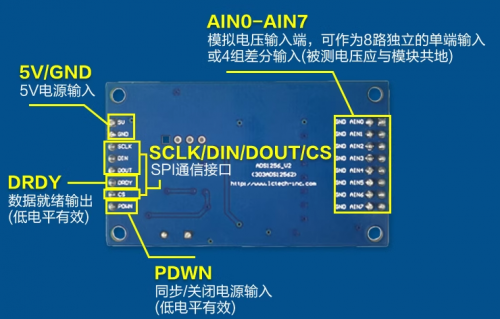
| 5V, GND | 5V power input |
| SCLK, DIN, DOUT, CS | SPI communication interface |
| DRDY | ADS1256 data ready output (low level valid) |
| PDWN | ADS1256 synchronous/off power input (low level valid) |
| AIN0-AIN7 | Analog voltage input terminal, can be used as 8 independent single ended inputs or 4 sets of differential inputs (the measured voltage should be grounded with the module). |
Due to the fact that the power supply voltage of ADS1256 is 5V, and the measured voltage should be 2V lower than the power supply voltage, the module is only suitable for measuring analog voltages within 3V< br>
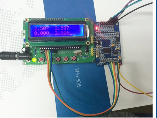
The module provides reference programs for STC15W&&STM32 microcontroller 8-channel serial port display and STC89C52 microcontroller 4-channel 1602-LCD display. The simple testing method for STC89C52 microcontroller+1602LCD LCD is as follows:
5V and GND are connected to a DC 5V power supply. SCLK, DIN, DOUT, DRDY, and CS are respectively connected to P1.2, P1.3, P1.4, P1.5, and P1.6 of the microcontroller. AIN0, AIN1, AIN2, and AIN3 are respectively connected to 2.5V, 2.5V, 2.5V, and 2.5V (the measured voltage should be grounded with ADS1256)
Four sets of voltage values will be displayed on the 1602 LCD, with the first, second, and fourth sets being the single ended input voltage values of AIN0, AIN1, and AIN3, and the third set being the difference between AIN2-AIN3. The four voltage values are approximately 2.5V, 2.5V, 0V, and 2.5V, respectively
Precautions
Due to the fact that the power supply voltage of ADS1256 is 5V, and the measured voltage should be 2V lower than the power supply voltage, the module is only suitable for measuring analog voltages within 3V.
Download User Manual
For more information on the use of this product, please refer toBaidu Netdisk Extraction code: liay